Product images are for illustrative purposes only and may differ from the actual product.
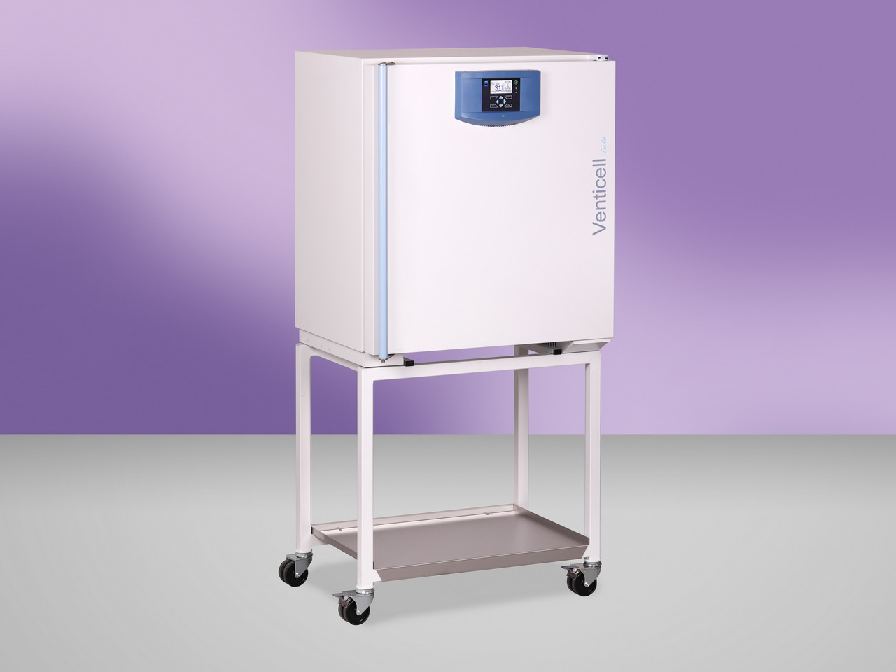
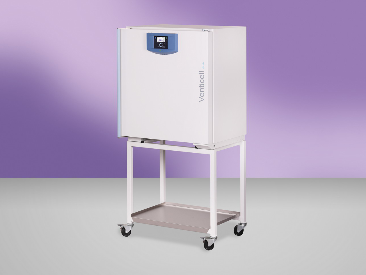
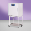
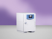
precise and fast laboratory drying oven
chamber volume 111 litres
temperature range from 10°C above ambient to 250/300°C
forced air circulation system in the chamber guarantees homogeneous temperature distribution in all the processes of drying, heating and sterilization of materials in laboratories
high operation comfort, precise temperature control and short chamber temperature equalization times after the door opening
higher speed and accuracy of all the tempering procedures ensures economical operation, especially suitable for high humidity materials, for demanding and accurate tests and processes
wide selection of optional equipment and accessories
Working temperature **) (beginning of the regulation) - VENTICELL / VENTICELL plus
from 10 °C above ambient temp. to
250 °C
Temperature accuracy according to DIN 12 880 T2, at working temperature with closed air flap and door, > 50 °C
time variation cca (±)
0,4 °C
space deviation (±) % cca (±)% of the reached temperature
1 %
Time required to reach 250 °C with closed air flap and voltage 230 V
53 min
Heat emission at 250 °C
760 W
Air exchange speed at 250 °C
49 cca/hour
Electricity - mains 50/60 Hz
max. power input
1,9 kW
nominal voltage
230 V
current
8,3 A
stand by
5 W
*) Approx. 50 % of the tray area can be filled in a way a uniform air circulation is enabled inside the chamber.Note: All technical data are related to 22 °C of ambient temperature and ±10 % voltage swing rate ventilator 100 %, defrost off, lighting off.
Changes in the design and make reserved. The values may differ depending on specific charge and media parameters.
Product images are for illustrative purposes only and may differ from the actual product.
Safety thermostat class according to DIN 12880 (user adjustable)
The protective thermostat is used to protect the exposed material, the device itself and its surroundings in the event of an unexpected course of regulation or failure. The temperature in the chamber is measured and evaluated by an independent control block. When the limits of the protection thermostat are exceeded, the heaters are disconnected from the mains voltage and the heating of the cabinet is stopped.
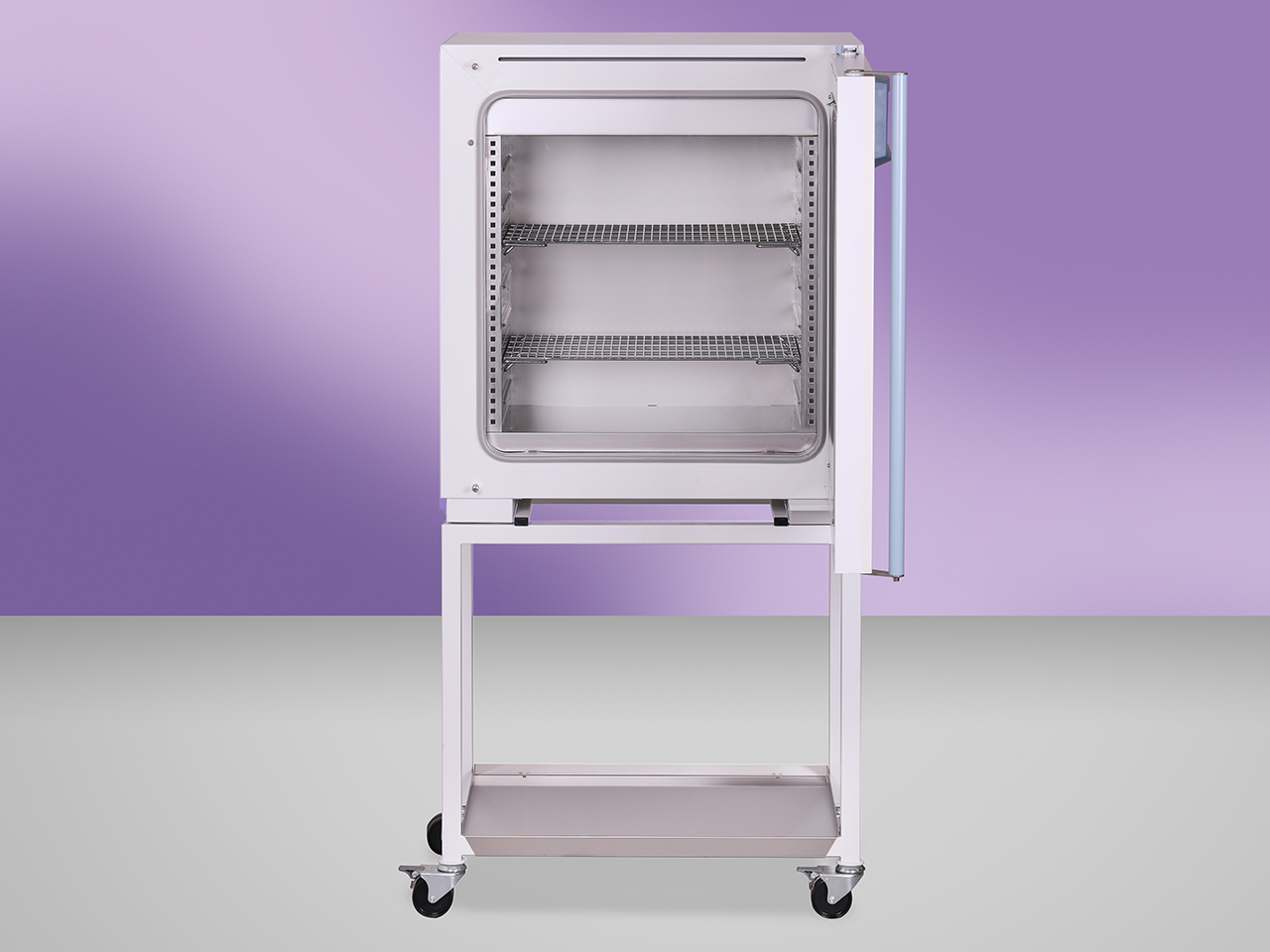
Chromed tray
Chrome steel tray for optimal air circulation
Stainless steel tray
AISI 304 stainless steel tray for optimal air circulation
Stainless steel shelf, perforated
Perforated shelf made of stainless steel AISI 304, suitable for placing a small-size sample in the chamber. The perforated shelf replaces the tray.
Chamber without tray holders and without trays
Can only be used in combination with some options (higher chamber load capacity, loading system, frame, 316 L) (except the volume 1212)
Test tubes holder (Loewenstein)
Special holders for test tubes in a diagonal position, typically for TBC testing. The holders are placed on ordinary trays. (except the volume 22)
Test tube shelf Ø 16 mm
Special holders for test tubes Ø 16 mm stored in a vertical position(except the volume 22)
Test tube shelf Ø 22 mm
Special holders for test tubes Ø 22 mm stored in a vertical position (except the volume 22)
Drip tub
Welded stainless steel tub for collecting condensate from samples in the chamber
Suspension system for samples under the chamber ceiling
Suspension system for longer samples (e.g. hoses) for hanging under the ceiling of the chamber for easier drying (except the volume 22)
Left door
Door hinges on the left. (except the volume 22, 1212)
Door lock (same key for order)
Mechanical door lock for the basic level of protection. It is supplied with two keys.
Door lock (different keys for order)
Mechanical door lock for the basic level of protection. It is supplied. Within one set of devices, different lock inserts are distinguished.
Automatic door lock
The device is equipped with an electromagnetic mechanism for blocking-locking the door. Can be operated manually or automatically. (except the volume 22)
Stainless steel shell
Stainless steel design of the device housing, including AISI 304 stainless steel handle
Flexible PT sensor
Additional movable sensor in the chamber for measuring the temperature at the sample or in the sample. It is not used for temperature control. The additional sensor data is shown on the display as an additional temperature value. (max. 1 pc)
Flexible PT sensor lead from the inner side of the door
Additional movable sensor from the door for measuring the temperature at the sample or in the sample. It is not used for temperature control. The additional sensor data is shown on the display as an additional temperature value.(max. 1 pc)
Flexible PT sensor at the temperature of 300°C
Additional movable sensor for higher temperatures.
Access port Ø 25 mm R (centre / centre)
The port with a stainless steel body allows the wires, sensors, etc. to be threaded into the chamber. Ø 25 mm located on the right in the middle of the wall.
Access port Ø 25 mm L (centre / centre)
The port with a stainless steel body allows the wires, sensors, etc. to be threaded into the chamber. Ø 25 mm located on the left in the middle of the wall.
Access port Ø 50 mm R (centre / centre)
The port with a stainless steel body allows the wires, sensors, etc. to be threaded into the chamber. Ø 50 mm located on the right in the middle of the wall.
Access port Ø 50 mm L (centre / centre)
The port with a stainless steel body allows the wires, sensors, etc. to be threaded into the chamber. Ø 50 mm located on the left in the middle of the wall.
Access port Ø 100 mm R (centre / centre)
The port with a stainless steel body allows the wires, sensors, etc. to be threaded into the chamber. Ø 100 mm located on the right in the middle of the wall. (except the volume 22)
Access port Ø 100 mm L (centre / centre)
The port with a stainless steel body allows the wires, sensors, etc. to be threaded into the chamber. Ø 100 mm located on the left in the middle of the wall. (except the volume 22)
Access port - special shape or position
The port with a stainless steel body allows the wires, sensors, etc. to be threaded into the chamber. Optional size, shape or position in the wall. (consultation required)
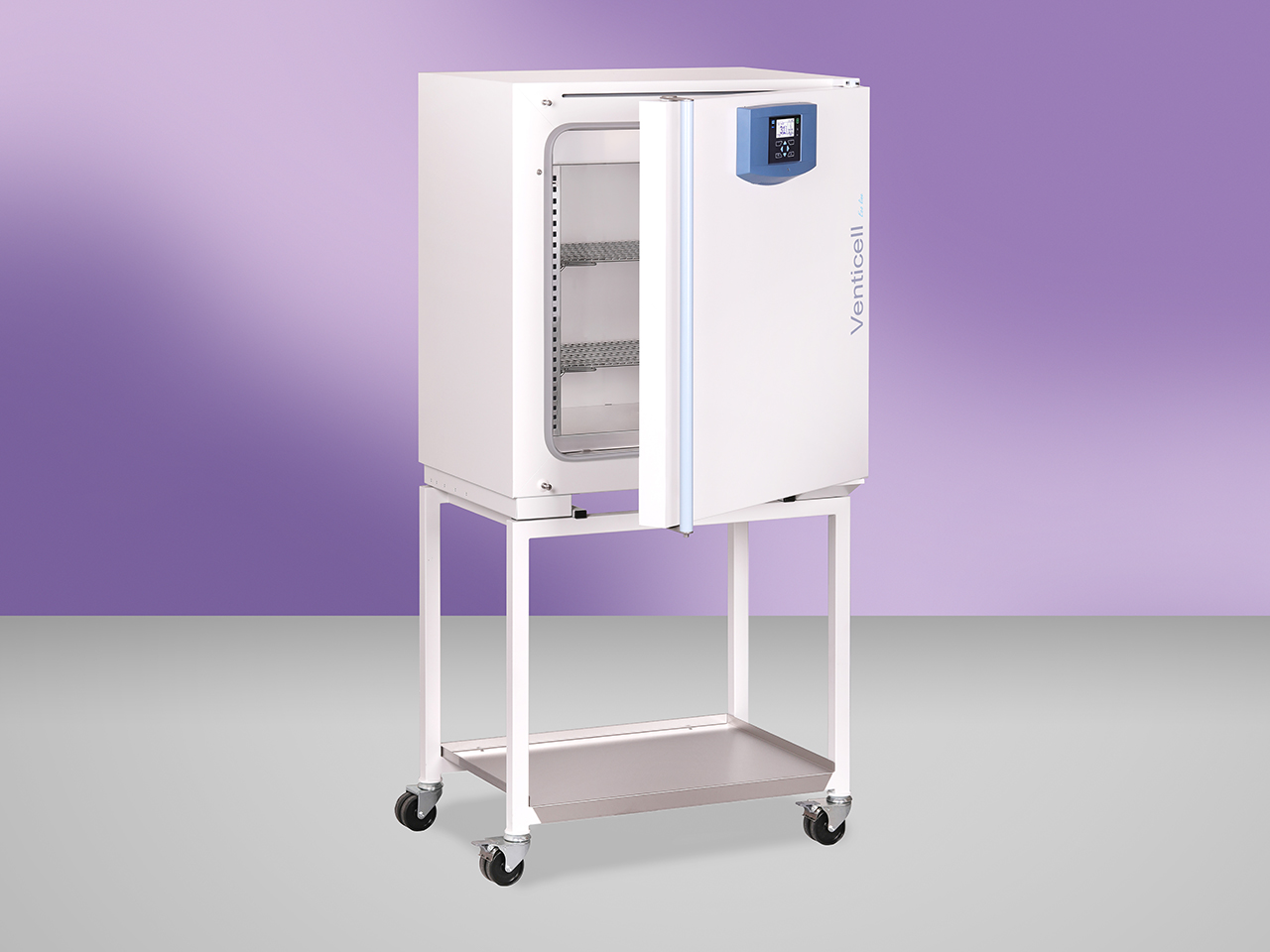
Window and interior lighting (max. up to 250°C)
Panoramic window with three-layer insulating glass enabling observation of samples in the chamber, complemented by mechanically switchable heat-resistant lighting of the chamber. (except the volume 22)
Interior lighting (no window)
Heat-resistant interior lighting with mechanical switch. (except the volume 22)
Pass-through version (including covering sheets on unloading side)
It allows loading of material in one space and its collection after heat treatment in another space - e.g. insertion in a non-sterile - "dirty" - space and collection after sterilization in a sterile - "clean" - space). Including cover plates for inserting the device into the wall on the unloading side. (except the volume 22, 1212)
Covering sheets for the loading side
Cover plates for mounting the device in the wall on the loading side (except the volume 22, 1212)
Special housing modification for insulator technologies
A set of mechanical modifications of the device for tight connection to the laboratory insulator. (consultation required) (except the volume 1212)
Loading system
Version with transport and loading cart (except the volume 22, 55, 111, 222 )
H13 HEPA filter 99,95%
Connection of the HEPA H13 filter to the inlet chimney of the device.
Overpressure in the chamber incl. HEPA H13
The overpressure HEPA H13 filter is equipped with an external fan, which pushes the ambient air through the HEPA filter into the chamber and thus ensures in the chamber an overpressure compared to the environment of about 20 Pa. During operation of the overpressure HEPA filter, the thermohomogeneity parameters may deteriorate.
H14 HEPA filter 99,995%
Connection of the HEPA H14 filter to the inlet chimney of the device.
Overpressure in the chamber incl. HEPA H14 99,995%
The overpressure inlet HEPA H13 filter is equipped with an external fan, without pressure regulation, with the possibility of setting the speed. May affect thermohomogeneity in the chamber.
Measurement of overpressure in the chamber
Only VC and only in combination with the option "Overpressure in the chamber incl. HEPA H14 99.995%" (consultation required)
Modification without particles
Sealing of the chamber and fan to prevent particles from entering the chamber from the outside.
Straight chimney extension
Extension for air outlet from the chamber for connection to external air conditioning (direct).
Chimney extension 90 °
Extension for air outlet from the chamber for connection to external air conditioning (bent - 90 °).
Extension for air outlet from the chamber for connection to external air conditioning (direct with condensate drain).
90 ° chimney extension (with condensate drain)
Extension for air outlet from the chamber for connection to external air conditioning (bent - 90 °, with condensate drain).
Automatic air flap (open / closed)
It can be closed or opened for a given program segment. The acoustic indication takes place when the ventilation flap is opened during the program run. Applies only to devices equipped with a damper switch. Allows you to close and open the flap of the ventilation openings of the device on program basis. (except the volume 22)
Modification of the device with wheels for adjustable feet
Adaptation of the device with castors to adjustable legs for greater stability. (except the volume 22, 55, 111, 222)
Modification of the device without wheels to wheels
Adjusting the device without castors to a device with castors for easier movement. (except the volume 22, 404, 707, 1212)
Wheels with extendable feet (leveling castors)
Adaptation of the device to adjustable castors for travel and greater stability. (except the volume 22)
Reinforcement of the device chamber and addition of a built-in frame with its own shelves to increase the load capacity of the device. (consultation required) (except the volume 22)
Increased load capacity of shelves
Special reinforced sheet metal shelves. (except the volume 22)
Increased load capacity of the chamber bottom
Reinforcement of the chamber bottom to increase the load-bearing capacity of the chamber sides. (consultation required) (except the volume 22)
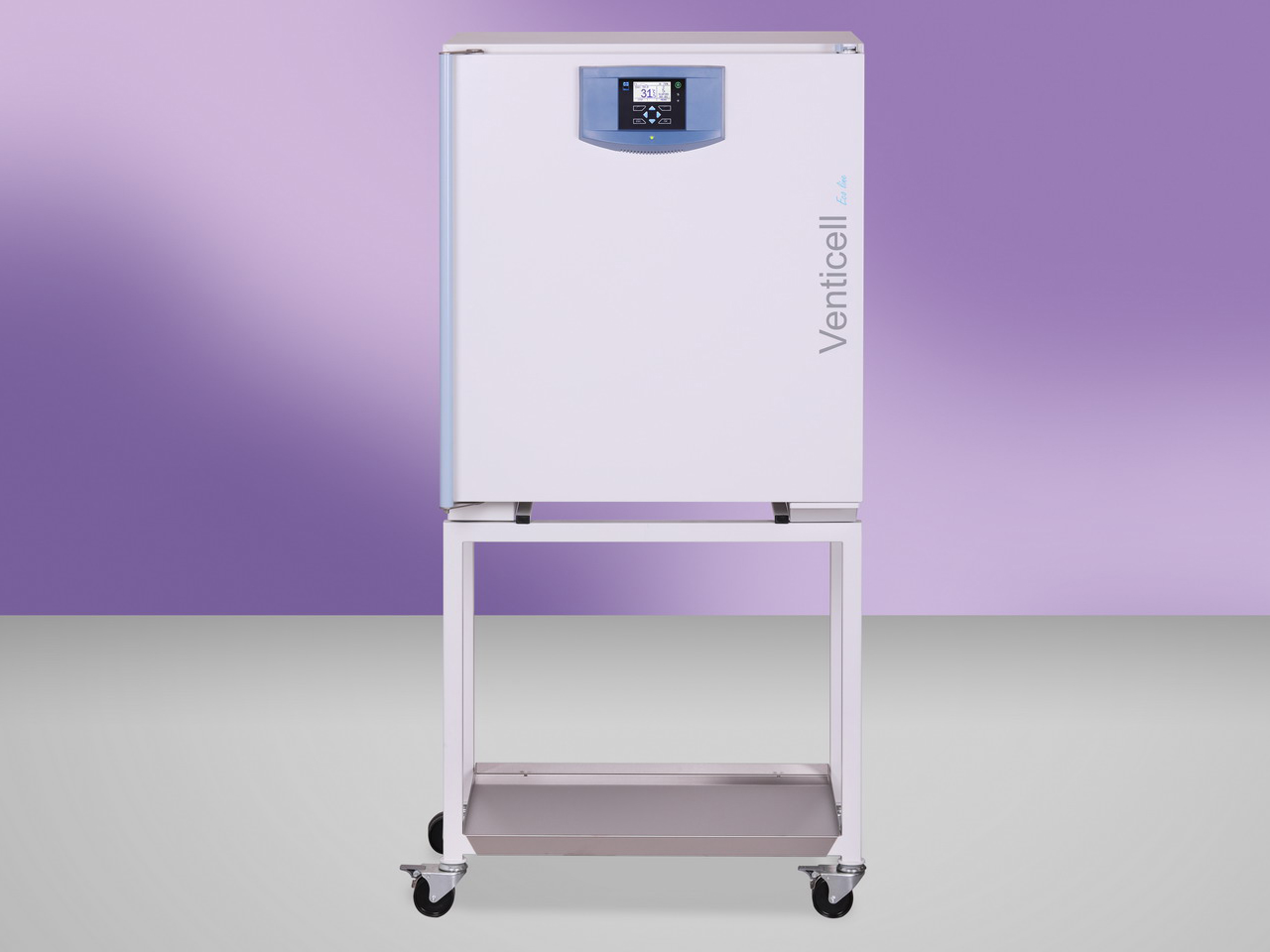
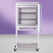
Device table
Mobile table in the design of the device for greater flexibility incl. shelf for storing documents. (except the volume 22, 404, 707, 1212)
Open door alarm
Door open notification, opening time can be set.
RAMPS
Programming function allowing to set the rate of temperature rise in ° C/min. Only with ECO PLUS and EVO. The ramp can be set as standard or aggressive. More in the instructions for use.
Aggressive heating
Service functions allowing to increase or decrease start times. This function can change the properties of the device.
ECO PLUS
The optional extension for Eco devices expands the number of segments from 2 to 8 for one program and allows temperature ramps to be defined within the program.
Internal socket max. 100°C (230 V, 3 A protection, IP67)
The socket (nominal voltage 230 V, fuse 3 A, protection IP67) is located inside the chamber on the side wall. (consultation required) (except the volume 22)
The potential-free contact is connected to a connector to which voltages up to 24 V / 1 A can be connected. It is used to implement a remote alarm (in Anglo-Saxon countries it is referred to as BMS relay - Building Management System relay) - i.e. a remote line that is interrupted by a built-in relay potential-free contact, the fault information is transmitted to rooms other than the one in which the temperature box is located. The relay opens in all error states reported on the display.
External flap switching
The signal for switching the external damper is fed to the relay coil behind the chamber. The relay contacts are connected to the connector in the rear leg or on the rear cover with electronics. The COM relay contact is connected to pin 2 of the connector. The NO relay contact is connected to pin 1 of the connector. The load capacity of the connector is 230 V / 10 A.
Emergency stop button
Hardware main switch with a lockable system, which, if necessary, interrupts the connection of electric power. (consultation required) (except the volume 22)
National design of the electric plug
Power supply termination supply according to the national standard (consultation required)
Operation temperature shift
Increasing the maximum working temperature to 300 °C (only stainless steel version for volumes of 404 l, 707 l)
Possibility of flash disk connection as an external data logger
The data logger requires the device to be equipped with a USB HOST interface, details in the Instructions for use of the device. It allows to record the time course of all measured quantities during the program run on the connected large-capacity USB device (FAT32 format). The data is saved with the selected period in CSV format. Subsequently, they can be processed by MS Excel, Access, etc.
Analogue output 4-20mA
The device contains a converter of the required quantity (temperature) to a 4-20 mA output, connected to a connector connection. It is not a quantity read by the instrument itself and converted to 4-20 mA. The customer processes the value himself and must also ensure the calibration of the sensors. Data cannot be collected using WarmComm.
Software Warmcomm 4 Basic (B)
"WarmComm 4 is designed to record the course of device control. The program uses the Server - Client arrangement. In this configuration, the monitored devices are connected to a Server that records and stores data obtained during control. Individual users then access this data through the Client. This arrangement can be implemented within a single PC, within a LAN or via the Internet or within a local network."
Software Warmcomm 4 Professional (P)
"WarmComm 4 is designed to record the course of device control. The program uses the Server - Client arrangement. In this configuration, the monitored devices are connected to a Server that records and stores data obtained during control. Individual users then access this data through the Client. This arrangement can be implemented within a single PC, within a LAN or via the Internet or within a local network."
Software Warmcomm 4 FDA (F)
"WarmComm 4 is designed to record the course of device control. The program uses the Server - Client arrangement. In this configuration, the monitored devices are connected to a Server that records and stores data obtained during control. Individual users then access this data through the Client. This arrangement can be implemented within a single PC, within a LAN or via the Internet or within a local network."
External printer
Use the EPSON TM-T20III to print the report.
Software PrinterArchiv
The Printer Archive program is intended for recording from the machine's print output. It serves as a direct replacement for a physical printer. The recording is in a fixed, preset format. Wider options for handling the recorded protocol, including archiving or printing to a desktop PC printer. Ordinary PCs with Windows XP and higher operating software can handle the hardware requirements. One free RS 232 (COM) port is required for each connected device. The maximum length of the connecting cable is 15 m. For more detailed requirements towards HW, get information from the dealer.
Internal temperature measurement, 1 point
Validation of the temperature distribution in the chamber at the user's reference temperature (1 point).
Measurement of temperature distribution, 3 points
Validation of the temperature distribution in the chamber at the user's reference temperature (3 points).
Temperature measurement, 9-point (DIN 12880)
Validation of the temperature distribution in the chamber at the user's reference temperature (9 points).
Temperature distribution measurement, 27-point (DIN 12880)
Validation of the temperature distribution in the chamber at the user's reference temperature (27 points).
Validation documentation
IQOQ dokumentation
Ethernet communication port for ECO
Optional equipment extends the communication capabilities of ECO devices with Ethernet.

")


")


")


")
")
")
")
")
")

")
")
")


")
")
")


")


")
 – remote alarm 24V/1A")


")
")
")


")
")


 VENTICELL® 22 - ECO line
 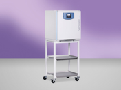 VENTICELL® 55 - ECO line
 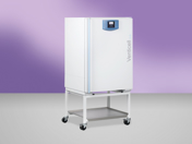 VENTICELL® 222 - ECO line
  VENTICELL® 404 - ECO line
  VENTICELL® 707 - ECO line
  VENTICELL® 1212 - ECO line