Product images are for illustrative purposes only and may differ from the actual product.
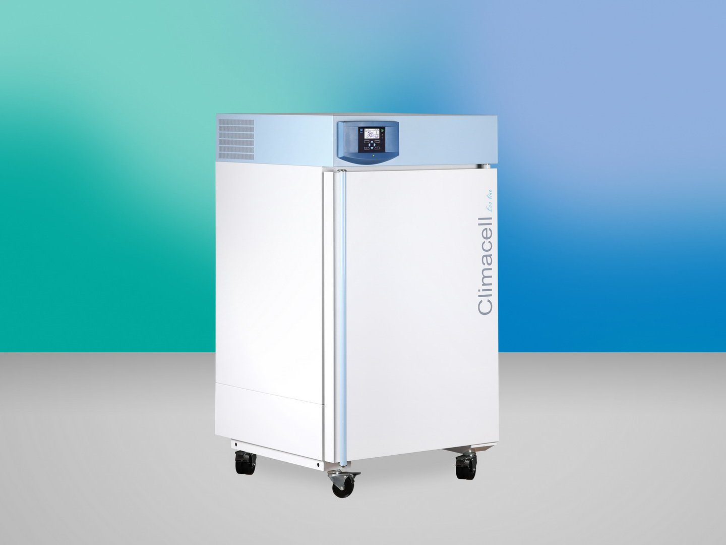
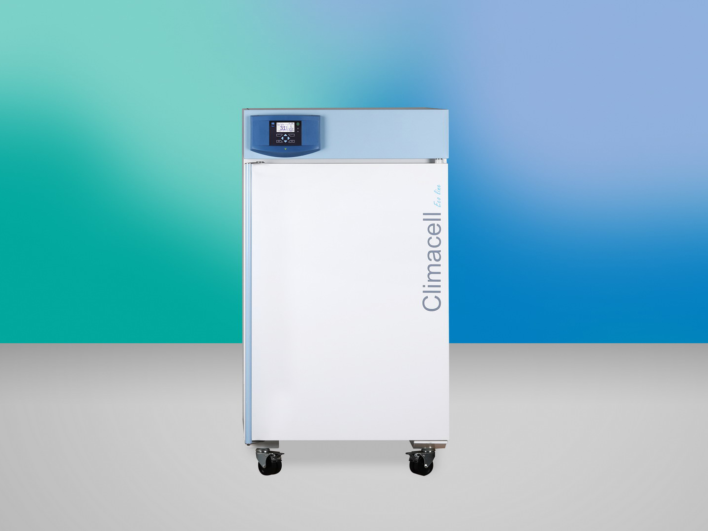
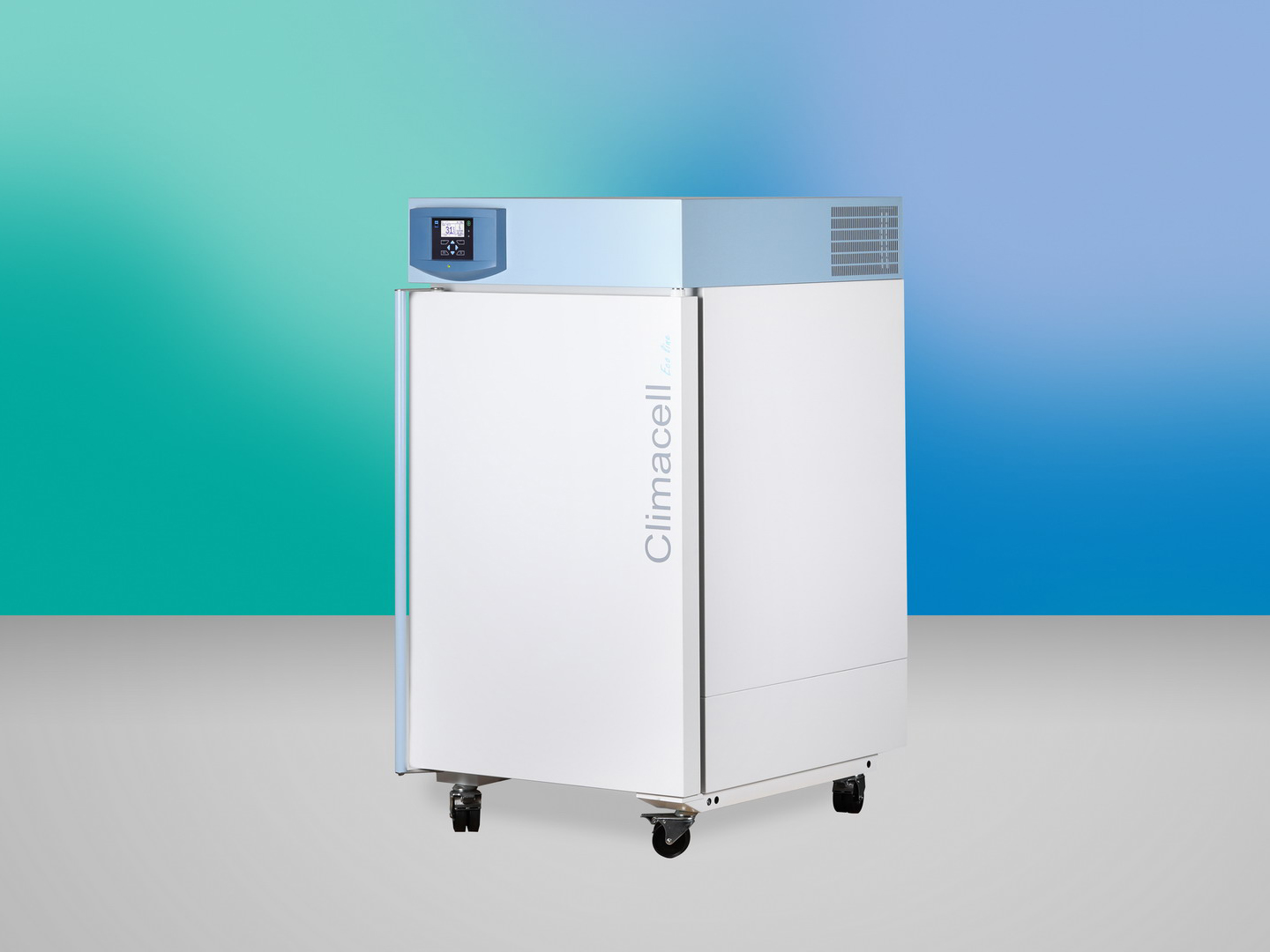
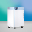
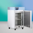
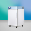
laboratory incubator – it always creates the right climate
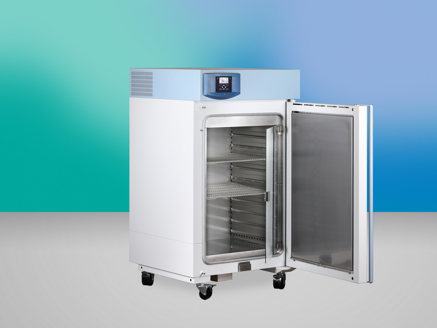
chamber volume 222 litres
temperature range: from 0°C to 100°C without humidity, from 10° C to 90° C with humidity
patented cooling system (environment-friendly working medium R 134a) and air flow in the chamber ensure fast and accurate distribution of the selected temperature and humidity in the chamber and thus the ideal process of sample heating and reduction of moisture condensation in the chamber
offers high operation comfort, precise temperature control, possibility of achieving extremely short times of temperature changes and short times of temperature and humidity equalization in the chamber after the door opening
suitable for use in research on germs, plant or tissue cultures, insects, stability tests, etc.
comfortable design with multi-processor Fuzzy logic control system, controls placed on a foil keyboard, process information displayed on LED display.
wide selection of optional equipment and accessories
Heating/up time to 37 °C from the ambient temperature
11 min
Working temperature from 0,0 to
100 °C
Working temperature from -20 to
100 °C
Temperature accuracy - in time
0,2 ± °C
Temperature accuracy in time at 10 °C
< 0,5 ±°C
Temperature accuracy in time at 37 °C
< 0,5 ±°C
Recovery time after 30 sec. door open according DIN 12 880
at 37 °C
3 min
at 50 °C
6 min
Relative humidity
range
10–98 %
Heat emission
at 37 °C
63 W
Outer dimensions (incl. Door and handle, and Rollers)
depth
895 mm
width
760 mm
height
1370 mm
Weight
brut cca
184 kg
nett cca
135 kg
*) Approx. 50 % of the tray area can be filled in a way a uniform air circulation is enabled inside the chamber.Note: All technical data are related to 22 °C of ambient temperature and ±10 % voltage swing rate ventilator 100 %, defrost off, lighting off.
Changes in the design and make reserved. The values may differ depending on specific charge and media parameters.
Product images are for illustrative purposes only and may differ from the actual product.
Safety thermostat class according to DIN 12880 (user adjustable)
Separate measuring circuit protecting the process in case of failure of the main control circuit.
Stainless steel tray
AISI 304 stainless steel tray for optimal air circulation
Stainless steel shelf, perforated
Perforated shelf made of stainless steel AISI 304, suitable for placing a small sample in the chamber. The perforated shelf replaces the tray.
Chamber without tray holders and without trays
Can only be used in combination with some options (higher chamber load capacity, loading system, frame, 316 L) (except for the volume 1212 l)
Test tubes holder (Loewenstein)
Special holders for test tubes in a diagonal position, typically for TBC testing. The holders are placed on ordinary trays.
Test tube shelf Ø 16 mm
Special holders for test tubes Ø 16 mm stored in a vertical position
Test tube shelf Ø 22 mm
Special holders for test tubes Ø 22 mm stored in a vertical position
Drip tub
Welded stainless steel tub for collecting condensate from samples in the chamber
Suspension system for samples under the chamber ceiling
Suspension system for longer samples (e.g. hoses) for hanging under the ceiling of the chamber for easier drying
Left door
Door hinges on the left. The cabinet with a volume of 22, 404, 707 and 1212 liters is not supplied in the left version.
Door lock (same key for order)
Mechanical door lock for the basic level of protection. It is supplied with two keys.
Door lock (different keys for order)
Mechanical door lock for the basic level of protection. It is supplied. Within one set of devices, different lock inserts are distinguished.
Automatic door lock
The device is equipped with an electromagnetic mechanism for blocking-locking the door. Can be operated manually or automatically.
Stainless steel shell
Stainless steel design of the device housing, including the handle made of stainless steel AISI 304.
Flexible PT sensor (max. number)
Additional movable sensor in the chamber for measuring the temperature at the sample or in the sample. It is not used for temperature control. The additional sensor data is shown on the display as an additional temperature value. (max. 4 pcs)
Flexible PT sensor lead from the inner side of the door (max. number)
Additional movable sensor from the door for measuring the temperature at the sample or in the sample. It is not used for temperature control. The additional sensor data is shown on the display as an additional temperature value. (max. 1 pc) (consultation required)
Access port Ø 25 mm R (centre / centre)
The port with a stainless steel body allows the wires, sensors, etc. to be threaded into the chamber. Ø 25 mm located on the right in the middle of the wall.
Access port Ø 25 mm L (centre/centre)
The port with a stainless steel body allows the wires, sensors, etc. to be threaded into the chamber. Ø 25 mm located on the left in the middle of the wall. (except for the volume 404, 707, 1212)
Access port Ø 50 mm R (centre / centre)
The port with a stainless steel body allows the wires, sensors, etc. to be threaded into the chamber. Ø 50 mm located on the right in the middle of the wall.
Access port Ø 50 mm L (centre / centre)
The port with a stainless steel body allows the wires, sensors, etc. to be threaded into the chamber. Ø 50 mm located on the left in the middle of the wall. (except for the volume 404, 707, 1212)
Access port Ø 100 mm R (centre / centre)
The port with a stainless steel body allows the wires, sensors, etc. to be threaded into the chamber. Ø 100 mm located on the right in the middle of the wall.
Access port Ø 100 mm L (centre / centre)
The port with a stainless steel body allows the wires, sensors, etc. to be threaded into the chamber. Ø 100 mm located on the left in the middle of the wall. (except for the volume 404, 707, 1212)
Access port - special shape or position
The port with a stainless steel body allows the wires, sensors, etc. to be threaded into the chamber. Optional size, shape or position in the wall. (consultation required)
Window and interior lighting
Panoramic window with three-layer insulating glass enabling observation of samples in the chamber, complemented by mechanically switchable heat-resistant lighting of the chamber. (consultation required)
Interior lighting (no window)
Heat-resistant interior lighting with mechanical switch.
Special housing modification for insulator technologies
A set of mechanical modifications of the device for tight connection to the laboratory insulator. (consultation required) (except for the volume 1212)
Exhaust chimney
Additional stainless steel chimney for extracting odors from the device. (for connection of fine suction - may affect thermohomogeneity) (consultation required)
Modification of the device with castors for adjustable feet
Adaptation of the device with castors to adjustable legs for greater stability.
castors with extendable feet (levelling castors)
Adaptation of the device to adjustable castors for travel and greater stability.
Reinforcement of the device chamber and addition of a built-in frame with its own shelves to increase the load capacity of the device. (consultation required)
Increased load capacity of shelves
Special reinforced sheet metal shelves.
Increased load capacity of the chamber bottom
Reinforcement of the chamber bottom to increase the load-bearing capacity of the chamber sides. (consultation required)
RAMPS
Programming function allowing to set the rate of temperature rise in °C/min. Only for ECO PLUS. The ramp can be set as standard or aggressive. More in the Instructions for use.
Aggressive heating
Service functions allowing to increase or decrease start times. This function can change the properties of the device.
ECO PLUS
The optional extension for Eco devices expands the number of segments from 2 to 8 for one program and allows temperature ramps to be defined within the program.
Internal socket max. 100°C (230 V, 3 A protection, IP67)
Programmable waterproof socket inside the chamber for connecting appliances.
The potential-free contact is connected to a connector, to which a voltage of up to 24 V / 1 A can be connected to it in. It is used to implement a remote alarm (in Anglo-Saxon countries it is referred to as BMS relay - Building Management System relay), which is interrupted by a built-in potential-free contact relay, the fault information is transmitted to rooms other than the one in which the temperature box is located. The relay opens and switches on in all error states reported on the display.
Emergency stop button
Hardware main switch with a lockable system, which, if necessary, interrupts the connection of electric power. (consultation required)
National design of the electric plug
Power supply termination according to the national standard (consultation required)
Operation temperature shift
Different operating temperature range.
Possibility of flash disk connection as an external data logger
The data logger requires the device to be equipped with a USB HOST interface, details in the Instructions for use of the device. It allows to record the time course of all measured quantities during the program run on the connected large-capacity USB device (FAT32 format). The data is saved with the selected period in CSV format. Subsequently, they can be processed by MS Excel, Access, etc.
Cooling with defrosting up to 0°C
Compressor cooling system up to 0 °C with defrost for short (weeks) lower chamber temperatures
COOLING PLUS
Compressor cooling system up to 0 °C with defrost for long-term (months) lower chamber temperatures. (except for the volume 55, 111, 1212)
Strengthened cooling without defrosting (-10°C)
Enhanced compressor cooling system without automatic defrost.
Strengthened cooling with defrosting (-10°C)
Enhanced compressor cooling system with automatic defrost.
Exposition lighting VIS in the door
VIS fluorescent lamp panel (with programmable intensity for EVO, for ECO only programmable switch-off) located in the door of the device.
LED exposition lighting VIS in the door
Panel of LED lights VIS (with programmable intensity for EVO, for ECO only programmable switch-off) located in the door of the device.
Exposition lighting, shelves VIS
Horizontal panel of VIS fluorescent lamps (with programmable intensity for EVO, for ECO only programmable switch-off) located in the chamber.
Exposition lighting, shelves UV
Horizontal panel of UV fluorescent lamps (with programmable intensity for EVO, for ECO only programmable switch-off) located in the chamber.
Exposition lighting, shelves MIX
Horizontal panel of VIS + UV fluorescent lamps (with programmable intensity for EVO, for ECO only programmable switch-off) located in the chamber.
LED exposition lighting, shelves VIS
Horizontal panel of LED VIS lights (with programmable intensity for EVO, for ECO only programmable switch-off) located in the chamber.
Analogue output 4-20mA
The device contains a converter of the required quantity (temperature, humidity, CO2 concentration) to a 4-20 mA output, connected to a connector connection. It is not a quantity read by the instrument itself and converted to 4-20 mA. The customer processes the value himself and must also ensure the calibration of the sensors. Data cannot be collected using WarmComm.
Software Warmcomm 4 Basic (B)
WarmComm 4 is designed to record the course of device control. The program uses the Server - Client arrangement. In this configuration, the monitored devices are connected to a Server that records and stores data obtained during control. Individual users then access this data through the Client. This arrangement can be implemented within one PC or within a local network.
Software Warmcomm 4 Professional (P)
WarmComm 4 is designed to record the course of device control. The program uses the Server - Client arrangement. In this configuration, the monitored devices are connected to a Server that records and stores data obtained during control. Individual users then access this data through the Client. This arrangement can be implemented within one PC or within a local network.
Software Warmcomm 4 FDA (F)
WarmComm 4 is designed to record the course of device control. The program uses the Server - Client arrangement. In this configuration, the monitored devices are connected to a Server that records and stores data obtained during control. Individual users then access this data through the Client. This arrangement can be implemented within one PC or within a local network.
External printer
Use the EPSON TM-T20III to print the report.
Software PrinterArchiv
The Printer Archive program is intended for recording from the machine's print output. Serves as a direct replacement for a physical printer. The recording is in a fixed, preset format. wider options for handling the recorded protocol, including archiving or printing to a desktop PC printer. Ordinary PCs with Windows XP and higher operating software can handle the hardware requirements. One free RS 232 (COM) port is required for each connected device. The maximum length of the connecting cable is 15 m. For more detailed HW requirements, please contact your dealer.
Internal temperature measurement, 1 point
Validation of the temperature distribution in the chamber at the user's reference temperature (1 point).
Measurement of temperature distribution, 3 points
Validation of the temperature distribution in the chamber at the user's reference temperature (3 points).
Temperature measurement, 9-point (DIN 12880)
Validation of the temperature distribution in the chamber at the user's reference temperature (9 points).
Measuring of RH, 3 point
Validation of temperature and humidity distribution in the chamber at the user's reference temperature / humidity (3/1 point).
Temperature distribution measurement, 27-point (DIN 12880)
Validation of the temperature distribution in the chamber at the user's reference temperature (27 points).
Validation documentation
IQOQ documentation for implementation during installation at the customer.
Ethernet communication port for ECO
Optional equipment extends the communication capabilities of ECO devices with Ethernet.

")


")


")


")
")
")
")
")
")
")
")


")


")


")
 – remote alarm 24V/1A")


")
")


")
")
")


")

")


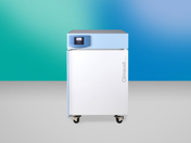 CLIMACELL® 111 - ECO line
 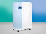 CLIMACELL® 404 - ECO line
 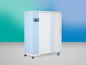 CLIMACELL® 707 - ECO line
  CLIMACELL® 1212 - ECO line