*) Approx. 50 % of the tray area can be filled in a way a uniform air circulation is enabled inside the chamber.
Note: All technical data are related to 22 °C of ambient temperature and ±10 % voltage swing rate ventilator 100 %.
Changes in the design and make reserved. The values may differ depending on specific charge and media parameters.
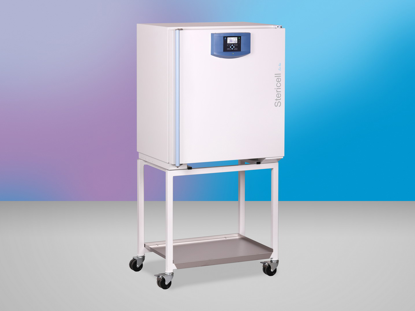
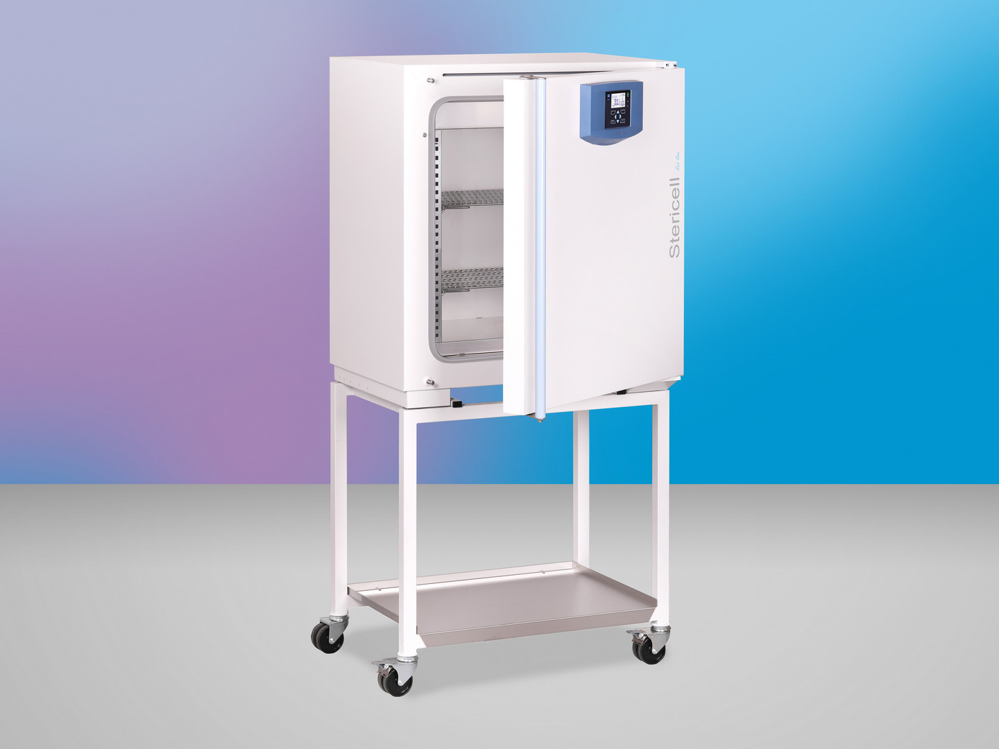
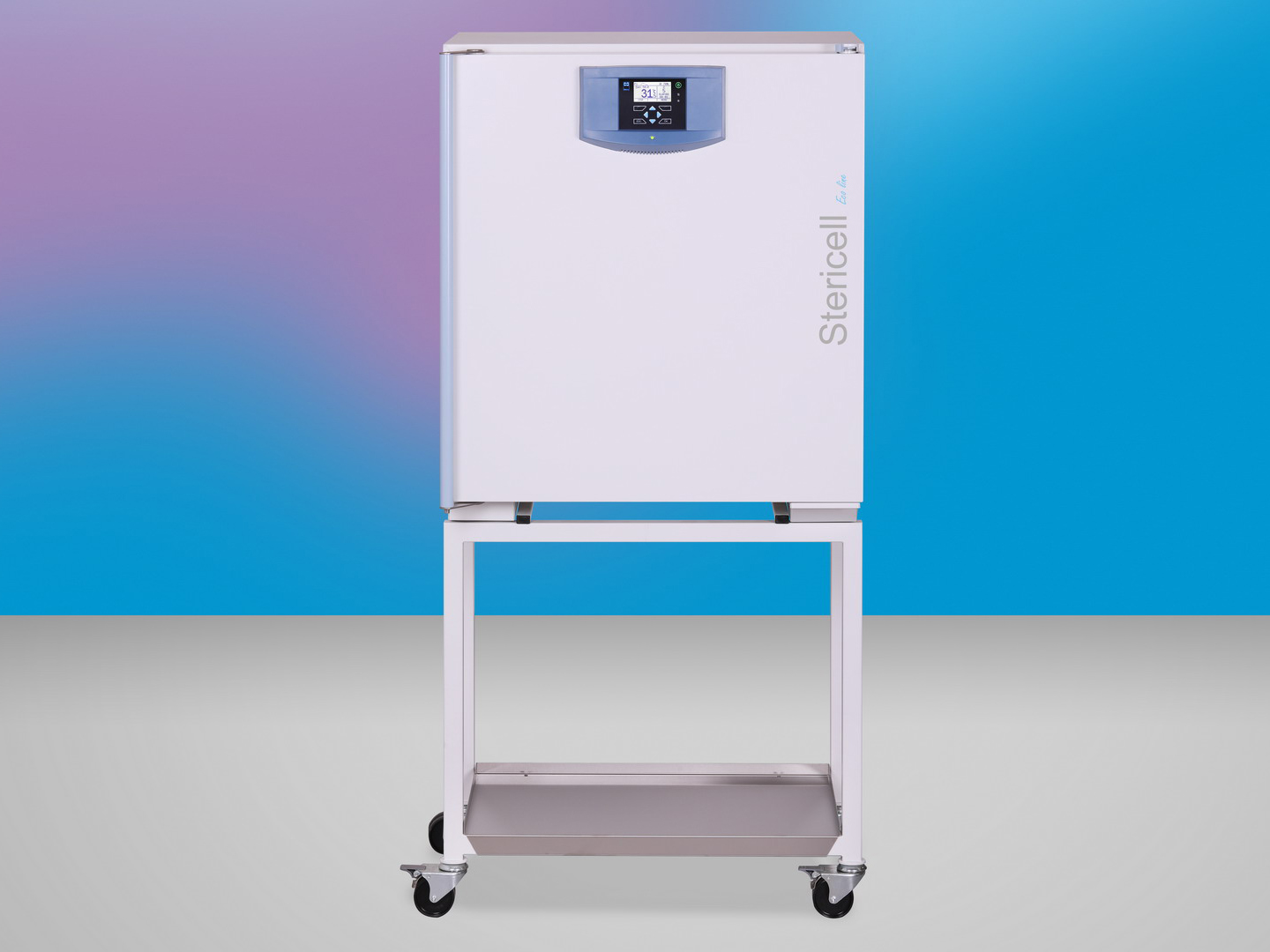
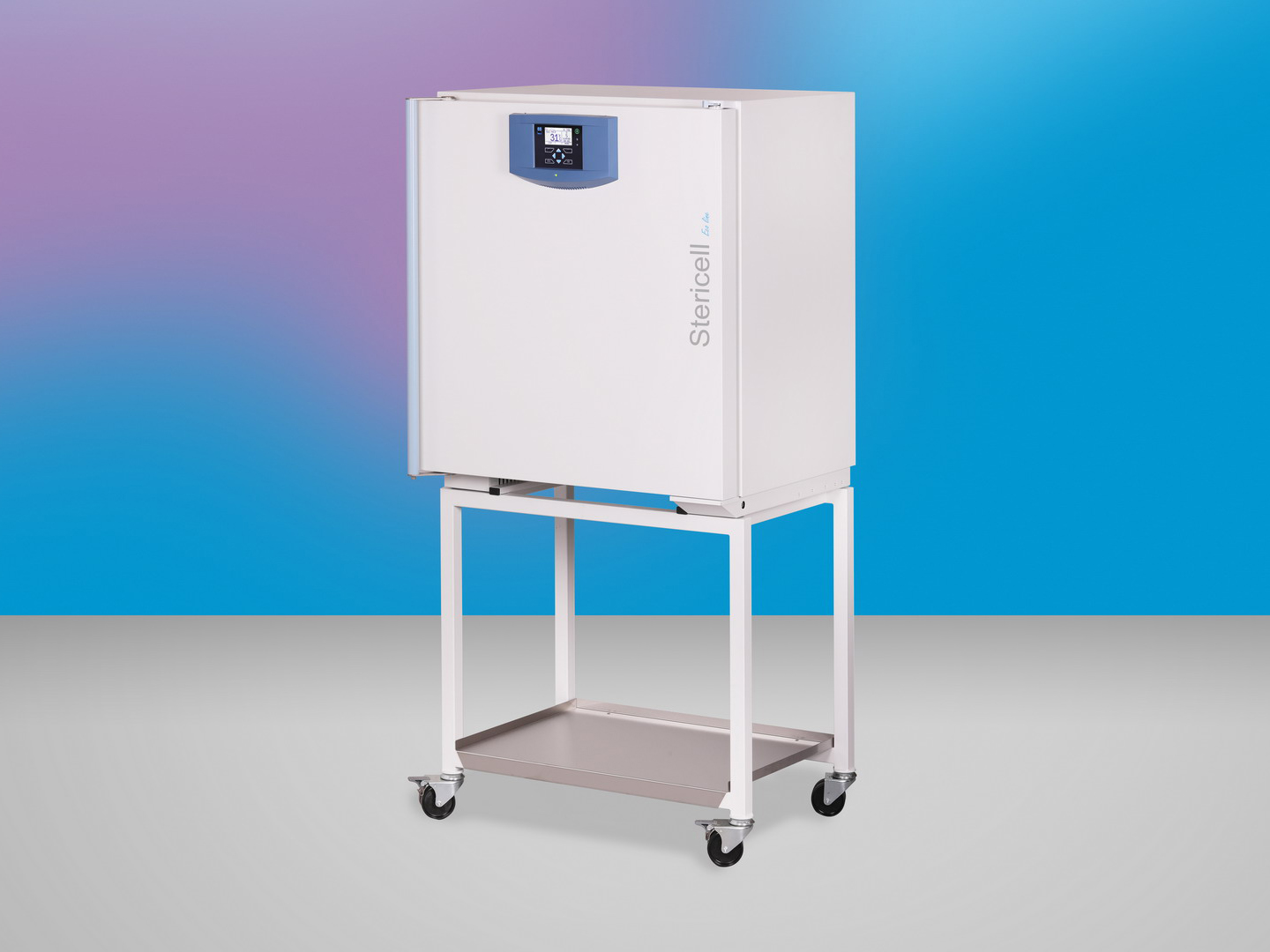
Product images are for illustrative purposes only and may differ from the actual product.
Safety thermostat class according to DIN 12880 (user adjustable)
The protective thermostat is used to protect the exposed material, the device itself and its surroundings in the event of an unexpected course of regulation or failure. The temperature in the chamber is measured and evaluated by an independent control block. When the limits of the protection thermostat are exceeded, the heaters are disconnected from the mains voltage and the heating of the cabinet is stopped.
Chromed tray
Chrome steel tray for optimal air circulation
Stainless steel tray
AISI 304 stainless steel tray for optimal air circulation
Stainless steel shelf, perforated
Perforated shelf made of stainless steel AISI 304, suitable for placing a small-size sample in the chamber. The perforated shelf replaces the tray.
Chamber without tray holders and without trays
Can only be used in combination with some options (higher chamber load capacity, loading system, frame, 316 L)
Test tubes holder (Loewenstein)
Special holders for test tubes in a diagonal position, typically for TBC testing. The holders are placed on ordinary trays. (except the volume 22)
Test tube shelf Ø 16 mm
Special holders for test tubes Ø 16 mm stored in a vertical position (except the volume 22)
Test tube shelf Ø 22 mm
Special holders for test tubes Ø 22 mm stored in a vertical position (except the volume 22)
Drip tub
Welded stainless steel tub for collecting condensate from samples in the chamber
Suspension system for samples under the chamber ceiling
Suspension system for longer samples (e.g. hoses) for hanging under the ceiling of the chamber for easier drying (except the volume 22)
Left door
Door hinges on the left. The cabinet with a volume of 22 and 404 liters is not supplied in the left version.
Door lock (same key for order)
Mechanical door lock for the basic level of protection. It is supplied with two keys.
Door lock (different keys for order)
Mechanical door lock for the basic level of protection. It is supplied. Within one set of devices, different lock inserts are distinguished.
Automatic door lock
The device is equipped with an electromagnetic mechanism for blocking-locking the door. Can be operated manually or automatically. (except the volume 22) (For passing-trough versions 55-2, 111-2, 222-2 and 404-2, it is part of the basic equipment of the device)
Stainless steel shell
Stainless steel design of the device housing, including AISI 304 stainless steel handle
Flexible PT sensor
Additional movable sensor in the chamber for measuring the temperature at the sample or in the sample. It is not used for temperature control. The additional sensor data is shown on the display as an additional temperature value.(max. 1 pc)
Flexible PT sensor lead from the inner side of the door
Additional movable sensor from the door for measuring the temperature at the sample or in the sample. It is not used for temperature control. The additional sensor data is shown on the display as an additional temperature value. (max. 1 pc)
Access port Ø 25 mm R (centre / centre)
The port with a stainless steel body allows the wires, sensors, etc. to be threaded into the chamber. Ø 25 mm located on the right in the middle of the wall.
Access port Ø 25 mm L (centre / centre)
The port with a stainless steel body allows the wires, sensors, etc. to be threaded into the chamber. Ø 25 mm located on the left in the middle of the wall.
Access port Ø 50 mm R (centre / centre)
The port with a stainless steel body allows the wires, sensors, etc. to be threaded into the chamber. Ø 50 mm located on the right in the middle of the wall.
Access port Ø 50 mm L (centre / centre)
The port with a stainless steel body allows the wires, sensors, etc. to be threaded into the chamber. Ø 50 mm located on the left in the middle of the wall.
Pass-through version (including covering sheets on unloading side)
It allows loading of material in one space and its collection after heat treatment in another space - e.g. insertion in a non-sterile - "dirty" - space and collection after sterilization in a sterile - "clean" - space). Including cover plates for inserting the device into the wall on the unloading side. (except the volume 22)
Covering sheets for the loading side
Cover plates for mounting the device in the wall on the loading side (except the volume 22)
Special housing modification for insulator technologies
A set of mechanical modifications of the device for tight connection to the laboratory insulator. (consultation required) (except the volume 22)
Loading system
Version with transport and loading cart (except the volume 22, 55, 111, 222 )
H13 HEPA filter 99,95%
Connection of the HEPA H13 filter to the inlet chimney of the device.
H14 HEPA filter 99,995%
Connection of the HEPA H14 filter to the inlet chimney of the device.
Straight chimney extension
Extension for air outlet from the chamber for connection to external air conditioning (direct).
Chimney extension 90 °
Extension for air outlet from the chamber for connection to external air conditioning (bent - 90 °).
Extension for air outlet from the chamber for connection to external air conditioning (direct with condensate drain).
90 ° chimney extension (with condensate drain)
Extension for air outlet from the chamber for connection to external air conditioning (bent - 90 °, with condensate drain).
Automatic air flap (open / closed)
It can be closed or opened for a given program segment. The acoustic indication takes place when the ventilation flap is opened during the program run. Applies only to devices equipped with a damper switch. Allows you to close and open the flap of the ventilation openings of the device on program basis. (except the volume 22)
Modification of the device with wheels for adjustable feet
Adaptation of the device with castors to adjustable legs for greater stability. (except the volume 22, 55, 111, 222)
Modification of the device without wheels to wheels
Adjusting the device without castors to a device with castors for easier movement. (except the volume 22, 404)
Castors with extendable feet (levelling castors)
Adaptation of the device to adjustable castors for travel and greater stability. (except the volume 22)
Device table
Mobile table in the design of the device for greater flexibility incl. shelf for storing documents. (except the volume 22, 404)
Aggressive heating
Service functions allowing to increase or decrease start times. This function can change the properties of the device.
The potential-free contact is connected to a connector to which voltages up to 24 V / 1 A can be connected. It is used to implement a remote alarm (in Anglo-Saxon countries it is referred to as BMS relay - Building Management System relay) - i.e. a remote line that is interrupted by a built-in relay potential-free contact, the fault information is transmitted to rooms other than the one in which the temperature box is located. The relay opens in all error states reported on the display.
National design of the electric plug
Power supply termination supply according to the national standard (consultation required)
Export of protocols to USB flash drive
If the SC ECO is equipped with a USB Host interface, it is possible to connect a USB device (FAT32 format) and export the last protocol or the last 100 protocols to it (the protocol of the drying and sterilization program is not distinguished). The logs are in PRNS format and are intended for reading in the Printer Archive.
External printer
Use the EPSON TM-T20III to print the report.
Software PrinterArchiv
The Printer Archive program is intended for recording from the machine's print output. It serves as a direct replacement for a physical printer. The recording is in a fixed, preset format. Wider options for handling the recorded protocol, including archiving or printing to a desktop PC printer. Ordinary PCs with Windows XP and higher operating software can handle the hardware requirements. One free RS 232 (COM) port is required for each connected device. The maximum length of the connecting cable is 15 m. For more detailed requirements towards HW, get information from the dealer.
Internal temperature measurement, 1 point
Validation of the temperature distribution in the chamber at the user's reference temperature (1 point).
Measurement of temperature distribution, 3 points
Validation of the temperature distribution in the chamber at the user's reference temperature (3 points).
Temperature measurement, 9-point (DIN 12880)
Validation of the temperature distribution in the chamber at the user's reference temperature (9 points).
Temperature distribution measurement, 27-point (DIN 12880)
Validation of the temperature distribution in the chamber at the user's reference temperature (27 points).
Validation documentation
The sterilization process must be validated by its user according to EN ISO 20857, Article 9.4.
Ethernet communication port for ECO
Optional equipment extends the communication capabilities of ECO devices with Ethernet.

")


")


")


")
")
")
")
")


")
")
")


")


 – remote alarm 24V/1A")


")
")


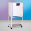
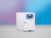 STERICELL® 22 ECO
 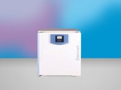 STERICELL® 55 ECO
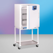
 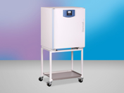 STERICELL® 111-2 ECO
 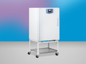 STERICELL® 222 ECO
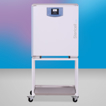
 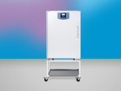 STERICELL® 222-2 ECO
 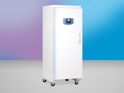 STERICELL® 404 ECO
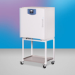
 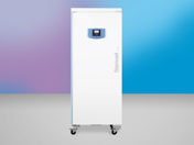 STERICELL® 404-2 ECO